 Free plan
Simple storage bin
533.4 mm × 533.4 mm × 444.5 mm
Cut list
| Part | Qty | L × W × T (mm) | Note |
|---|---|---|---|
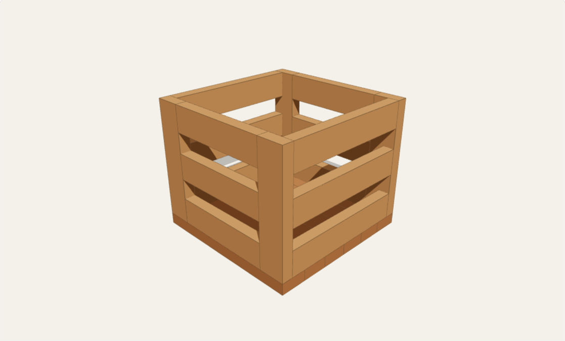
| Corner post — nominal 2×4 | 4 | 406.4 × 88.9 × 38.1 | Step 1: cut four square-ended posts to 406.4 mm. All twenty-two timber blanks use finished 38.1 mm × 88.9 mm stock, not nominal machining dimensions. Acclimate dry, straight lumber, measure the actual stock and allow extra for saw kerfs, end trimming, defects and any jointing loss; this is not a no-waste shopping layout. Each post presents its 88.9 mm face across the bin width and its 38.1 mm thickness along the depth. The post bottoms will sit on the floor boards at 38.1 mm above the ground and their tops finish at 444.5 mm. At the default settings the source timber envelope is 533.4 mm × 533.4 mm × 444.5 mm, without casters; changing width or height adapts that plan while keeping the depth and stock fixed. |
| Front / rear rail — nominal 2×4 | 6 | 355.6 × 88.9 × 38.1 | Step 2: build matching front and rear panels. Fit three 355.6 mm rails on edge between each pair of posts, with outside faces flush and each rail's 88.9 mm dimension vertical. Measured from the eventual underside of the floor, rail bottoms are 38.1 mm, 196.85 mm and 355.6 mm. Equivalently, the lowest rail is flush with the post bottoms and the highest is flush with their tops; leave a clear 69.85 mm gap between tiers. Use matching spacers and check both panel diagonals. Set a pocket-hole jig for 38.1 mm stock and use two 63.5 mm pocket screws at each rail end, twenty-four here. Test the jig, screw length and placement on offcuts before drilling; keep pockets away from the later side-rail connections. Glue these frame joints only, clamp square, and follow the jig and screw manufacturers' guidance. |
| Side rail — nominal 2×4 | 6 | 457.2 × 88.9 × 38.1 | Step 3: join the panels with three 457.2 mm side rails on each side. These stand on edge with their outside faces flush to the outer width faces of the posts. They span between the inner front and rear post faces, from 38.1 mm to 495.3 mm along the depth; do not shorten them by the posts' wider dimension. Match all three elevations and the 69.85 mm clear tier gaps on the front and rear. Glue the frame joints and use two pocket screws at each rail end, twenty-four here. Stagger pockets clear of the front/rear rail screws, confirm adequate wood around every screw and no exposed tips, and keep the lower edges coplanar while comparing the frame diagonals. Let the frame glue cure before attaching the floor. |
| Floor board — nominal 2×4 | 6 | 533.4 × 88.9 × 38.1 | Step 4: place six 533.4 mm floor blanks flat beneath the frame, grain running across the bin width. Their 38.1 mm thickness supplies the bottom of the finished height. The six nominal 88.9 mm widths cover 533.4 mm front to rear; the viewer shows this nominal edge-to-edge layout, not installation clearances. IMPORTANT DEVIATION FROM SOURCE: do not glue the floor to the frame or glue adjacent floor boards together, and do not rigidly screw across their grain. Fit each board independently with seasonal clearance at its loose long edges, adjusting those edges after acclimation rather than forcing six tight boards into the fixed depth. Choose clearance for the wood species, moisture range and site conditions. Fasten upward through each board into the lower left and right side rails, keeping all screws within sound rail material and clear of the pocket joints. At each end, use one round clearance hole near that board's own cross-grain width centerline and a second clearance slot running front to rear, along z, to permit that board's width movement. Use suitable washers over the slots; slot travel, washer coverage, pilot holes, edge distances and tightening must suit the selected fastener and expected movement. Do not clamp the slotted connections so tightly that movement is prevented. Hardware, holes, slots and fitted edge gaps are not modeled. Sand sharp edges and splinters, apply a suitable finish, and inspect the completed joints before use. This bin has no structural load rating or child-safety compliance claim: the openings are not guaranteed to contain toys or other small objects, and nobody should climb, sit or stand inside. Optional casters are excluded from the model, parts list and height; select and install them only to their manufacturer's requirements, including mounting support, stability and braking. |
| Pocket-hole screw 63.5 mm | 48 | 63.5 × 4.8 × 4.8 | Frame assembly allowance, not a source-specified total: two screws at each end of twelve rails, forty-eight total. The source's pocket-hole option uses 63.5 mm screws; the listed 4.8 mm diameter is nominal. Select pocket screws and thread type compatible with the actual wood, 38.1 mm stock and chosen jig. Test on offcuts and avoid overdriving. These screws are for the glued frame joints, not the movement-permitting floor attachment. Wood glue, finish, washers and any optional caster hardware must be bought separately. |
| Floor-attachment screw 63.5 mm | 24 | 63.5 × 4.8 × 4.8 | Separate floor-attachment allowance: two screws at each end of six boards, twenty-four total. Nominal 63.5 mm length and 4.8 mm diameter are selection starting points, not a verified connection specification. Select non-countersinking heads and compatible washers that bridge the z-direction slots throughout their travel without binding. Account for washer thickness, the 38.1 mm floor and required embedment in the lower side rails; verify pilot size, edge distances, screw locations and no breakout on offcuts. One hole at each end fixes each board near its own width centerline; the other hole at that end is slotted to allow independent cross-grain movement. Follow the fastener manufacturer's guidance and retain movement after tightening. Do not substitute the source's rigid glued bottom attachment. Inspect periodically for loose joints, splitting or movement restrictions; no safe working load is specified. |
About this plan
An open-top storage bin built from twenty-two square-cut 2×4 pieces: four corner posts, three rails on each wall and six full-width bottom boards. The front and back rails butt against the posts' narrow 38.1 mm edges; side rails span between the posts' broad inner faces to join those assemblies. This beginner-to-intermediate pocket-hole project needs a saw, drill, clamps and a weekend plus finish curing. It is for household storage, not seating, climbing or standing inside; no load rating or child-safety certification is provided. Small objects can pass through the open sides.
Customize width from 400–700 mm and overall height from 350–500 mm. Depth remains 533.4 mm, with fixed actual 38.1 × 88.9 mm stock and six floor boards. Rail spacing, post lengths, front/back rail cuts and floor lengths update with the 3D preview and cut list. Defaults match the source's 21 × 21 × 17½ inch bin without casters. The floor attachment deliberately allows seasonal wood movement instead of using the source's rigid cross-grain glue and screws. Casters and handles are optional, not rendered or included in the stated dimensions.
Questions
- Can I change all three dimensions?
- Width and height are customizable. Depth stays 533.4 mm because the floor uses six 88.9 mm-wide boards. The three wall-rail tiers stay fixed in count; their two equal clear gaps change with height.
- Are wheels and pulls included?
- No. Optional casters and handles must be selected and installed to their manufacturer's instructions. Casters add height and affect stability. Measure the full assembly against your storage opening; the preview and headline exclude them.
- Should the bottom boards be glued to the frame?
- No. Keep the floor boards independent and allow seasonal movement across their widths using the described washer-and-slot attachment. Do not glue the floor across the frame or glue neighboring floor edges together. Hardware and clearance slots are assembly operations, not rendered geometry.
- Will this fit under the simple storage table?
- Check both configured builds rather than assuming a fit. A default bin is 444.5 mm tall without wheels; the default table's lower apron begins at 520.7 mm. Two 533.4 mm-wide default bins total 1066.8 mm against the table's 1104.9 mm clear length. Added hardware and maneuvering clearance still need checking.